Wednesday, December 2, 2015

71. A Raspberry Pi Security Camera System

78,000 page views!!
I came across motionPie [this has now become motionEYE OS] some time ago and bookmarked it for later reference.  I only remembered it recently and looked into it in detail.  I discovered a fantastic system which is what I've been looking for for ages.

I've done live video via SSH HERE which was interesting, and even did control of LEDs via wireless network HERE but I hadn't realised that access to web pages on the internet is not possible unless you open a port on your router.  This is called Port Forwarding, and I've always been afraid to get involved in this by meddling with my router's settings in case I messed the whole thing up.

Anyway, this time I bit the bullet and had a go, and it worked!!  What I now have is an extremely cheap security camera system - with 2 cameras - and I can broadcast the live video images to the internet!

Camera 1 is the RasPi Camera at 1600 x 1200 pixels.  Camera 2 is the Logitech USB camera at 640 x 480 pixels.

The instructions for installing motionPie are very clearly given HERE by Gus of PI My LifeUP.  He also gives instructions for setting your router up for Port Forwarding HERE.  [The download page for motionEYE OS can be found HERE]. However, while the instructions give all the essential information, his router is not the same as my BT Infinity Hub 3.0 router.  So I went to my Home Hub web page and the information there is also useful, although after setting it up, you don't know whether your port is open or not.

However, I then found a useful site HERE which will confirm that your port is open and is not being blocked by the firewall.  There are of course other good sites with Port Forwarding testers.
Another program useful for showing you what devices are on your network is Zenmap available from HERE. Run it with a target of 192.168.1.0/24 and a command of nmap -sn 192.168.1.0/24.  This will list all the addresses of connected devices (hosts).

motionEye requires a dedicated SD card image on the Pi, because it is a stand-alone operating system (OS), but this is not a problem.  Once set up, you don't even need a monitor attached to the Pi, your motionEye console gives you access to everything you need, including downloading images to your PC and deleting images from the Pi.

The two cameras I am using are the RasPi Camera board, connected to the Pi through the CSI - camera serial interface - in the usual way, and a cheap USB camera I used to use for Skyping from my PC.  PI My LifeUP suggests that you can have even more USB cameras.  I will have to test that.

Here is an image of the control console [the motionEye console is almost identical, with some improvements]:
The available control options are too numerous to capture in one picture, but the image shows the main sections which open up and give almost total control of your video, stills, time lapse or motion activated images from all your cameras.

There's only one problem that I've noticed after running this for a couple of days  - my router port has for some reason closed a couple of times (it changed its IP address once too - maybe is this what is meant by Dynamic DNS - Dynamic Domain Name System?).  When this happens, you no longer have the ability to re-boot the Pi through the motionEye console.  If the Pi were to be placed somewhere remote, you would have to go to it and de-power and re-power it to get the system running again.  This is just something to bear in mind.

I have added a couple of time-lapse sequences (conveniently produced by motionPie/motionEye) below:

Camera 1:
Camera 2:
Here's a photo of the Pi with the RasPi Camera looking through my 8X zoom Telephoto lens.  You can see the cable running up to the USB camera which is looking through the window higher up.


Have a close look at this picture and see if you notice that pesky Jay bird nosing about.

Here he is pinching the tits' lunch:
Nice bird - a type of crow, and related to the magpie - apparently not that common in this part of the world - except my garden!  They are said to be "shy woodland birds" - this one's anything but shy.  I must report him to the RSPB!

motionEye is a really super piece of software.

Saturday, November 21, 2015

70. The 4-digit 7-segment LED Display Revisited

46,000 page views!!
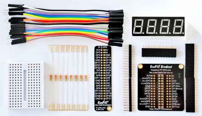
In a previous post (see HERE) I used an Arduino to drive a 4-digit, 7-segment LED display to count down from 9999 seconds to zero.  Just a few days ago, Alex Eames of RasPi.TV blogged (see HERE) to say that he managed to drive one of these displays with a Raspberry Pi and make it into a real-time clock.  In fact, he also offered a kit of parts to carry this out, so I bought one (only £12 including postage).  Here's the kit:


I thought this was interesting because other real time clocks I have built, have had a small circuit board powered by a separate button battery to keep the clock going even when the main board is switched off.  (See HERE.)  I wondered how you could do this even with a Raspberry Pi as, like the Arduino, it doesn't have a built in clock either.

The secret is that the Raspberry Pi is on-line and the Python language's time library is capable of reading the time at regular intervals from the internet, using the time.ctime() function.  This had been previously reported just about a year ago by bertwert (see HERE).

The details of Alex's kit can be found in his blog, referenced above, so I'll not repeat them here.

Common Cathode

Here is the kit assembled and connected to my Raspi B+:


Note that the Pi has a WiFi dongle and is connected to my wireless network.  You can see the LED Display unit mounted on the mini-breadboard, and the 8x 100 Ω resistors, all supplied by Alex.

Here's a video:
PB193845 from Vimeo.

And here's my version of Alex's code which was derived from that of  bertwert:

You can see from lines 38 to 51 that the time.ctime() command is repeatedly executed, reading the time from the internet, in the form Sat Nov 21 17:11:05 2015’.  
This is parsed to extract just the hour (17) and the minutes (11) and display these four digits.  The decimal point for the second digit (digit 1) is used to separate the minutes from the seconds and to flash every second.

The code loops, for each digit, each of its segments, and depending on whether the num dictionary specifies that segment to be 0 or 1 ie off or on, switches that segment on for 5 milliseconds.  This happens very fast, so each segment to go on, actually flashes on for 5 milliseconds in each loop.  This time.sleep(0.005) command is repeatedly executed until the time read from the internet changes (for example another second is updated).  So the LEDs are actually flashing repeatedly.  This is a form of Pulse Width Modulation, and the eye-brain system of an observer doesn't notice the flashes, but observes the segment of the digit as a steady light of constant brightness, even though the brightness of the flashes is much higher.  This has been described before as Persistence of Vision (POV).

Alex of course, goes on (see HERE) to make a count-down ticker, but still dizzy with excitement, I remembered that I had a spare 4-digit 7-segment LED Display so I dug it out.  It is of a different type, COMMON ANODE, as opposed to the COMMON CATHODE one above supplied by Alex.

So I started wondering how I could wire up my spare LED display, and realised that there was more to it than just a simple swap-over.  Before I risked blowing anything up, I consulted Alex.

Here is the internal circuit diagram for the COMMON CATHODE oue:
The diodes are arranged so that for each digit, DIG.1, DIG.2, DIG.3 and DIG.4, the cathodes are all connected together (to pin 12 for DIG.1, pin 9 for DIG.2 etc). Using wiring paths in this way, ie the same wires doing different things depending on the software logic, is known as multiplexing.

Here is the wiring diagram for the Common Cathode display:


Common Anode

The COMMON ANODE one looks like this:
Notice that the diodes are pointing from anodes which are common for each digit's 7 segments and decimal point, DP1, DP2, DP3 and DP4.  Also notice that there is a colon (L1 and L2) and an apostrophe (L3), but they aren't used here.

Here's my COMMON ANODE display connected to my Raspberry Pi 2:

You can just about see my black mini-breadboard with the resistors (this time 8x 680 Ω).

Here's a video:

Here's the code for the COMMON ANODE setup:


Notice that a few changes have been made, mostly changing 0's to 1's and 1's to 0's. You'll see on Alex's post that I asked him for advice in doing this part, and he kindly responded and put me on the right track.  Thanks again Alex!

Here's the wiring diagram for the Common Anode Display:
And here is the Common Anode Display wired through the RasPiO Duino.  The Duino doesn't have anything to do with the 4-digit, 7-segment LED Display, but in fact it is running a sketch which is driving a darkness-enabled mood lamp (see the mood lamp made HERE previously):
Here's a video of this circuit working:

PB233854 from Vimeo.
The next step I want to make is to drive the LED Display with the Duino, which hopefully will be getting the time information from the internet via the Raspberry Pi.  Watch this space!

Thursday, October 1, 2015

69. The Sense HAT's Inertial Measurement Unit

45,000 page views!!
I described this HAT (Hardware Attached on Top) for the Raspberry Pi a couple of posts ago (HERE).  Among its many goodies are a gyroscope, which measures momentum and rotation, an accelerometer which measures acceleration forces including that due to gravity, and a magnetometer, which measures the earth's magnetic field.

These three sensors make up what is collectively described as an Inertial Measurement Unit (IMU).  I have described the operation of the IMU in a previous post (No 53 HERE).  Three orthogonal axes are chosen, and rotational directions around these axes are known as rollpitch and yaw.  Here is an illustration of the roll, pitch and yaw rotations of the Pi with the HAT fitted:

To further illustrate this, take as an example an aircraft, where roll describes the rotation about the direction of travel.  For example, when the wings go up on one side and down on the other: pitch is the motion when the nose of the plane goes up or down, and yaw describes a left or right turn.  They are the three orthogonal axes about which rotation of any object can be made, and combined rotations around all three axes give all the possible orientations that any body can have.  Here's a useful video to describe this:


So when the Raspberry Pi with its HAT on is tilted in various directions, the IMU can detect this and send the orientation data to the Raspberry Pi which can run software to represent this on a display.

I wrote a little Python script to make use of the 8 x 8 RGB LED display to indicate two of the rotations, pitch and roll.  Trying to represent yaw as well as pitch and roll on a 2D display is too difficult!  Here's the video:


You can see that my Pi 2B has the Raspberry Pi Camera Board attached, even though that's not needed for this project.

Here's my code:

While I was at it, I thought I would load up the 3D Apollo-Soyuz Demo, and it works well.  Here's the video (watch out for my thumb!):

You will have seen that I also have the 8 x 8 RGB LED array lit up, even though this also is not part of this project.

At the later part of the above video, I used the keyboard key " = " to rotate (yaw) the spacecraft in a clockwise direction.  I could equally have used the " - " key to offset the yaw of the spacecraft in a counter-clockwise direction.  Other keys that can be used are " a " which will toggle the accelerometer on and off, " g " to toggle the gyroscope on and off, and " m " to toggle the magnetometer on and off.  See how this facility is included in the code below (lines 62 to 74) by Ben Nuttall of the Raspberry Pi Foundation:
The code uses a file apollo-soyuz.obj which has all the necessary details of the spacecraft model to generate the display. Apparently it's possible to use Sketchup or Blender to make models and use them like this.  I must have a go at that!

Here is a depiction of the 1975 spacecraft of the first joint Soviet-USA space flight - Apollo /Soyuz  (and also the last Apollo mission, the Space Shuttle taking over after that):

Note that the diagram refers to Apollo 18.  Apollo 18 was actually cancelled, and in this joint mission it was simply referred to as Apollo.  This Apollo-Soyuz Test Project was successful, but Apollo got into a spot of bother on re-entry.  You can read about it HERE.

The 3D Apollo-Soyuz Demo is supplied as part of the Sense HAT (Astro Pi) software repository on GitHub.  See HERE.

Thanks Ben!

Thursday, September 10, 2015

68. The RasPiO Duino HAT

44,000 page views!!
Here's the previously-mentioned HAT (Hardware Attached on Top) that has been developed by Alex Eames of RasPi.TV and RasP.iO.  This comes as a kit which is easy to solder together.  The aim with this was to make it easy to carry out Arduino programming on the Raspberry Pi.  So the scripts are in the Arduino language and are run on the built-in Atmel ATMEGA328P-PU (ie an Arduino) chip.

Having uploaded the Arduino sketch on the Arduino IDE from the Raspberry Pi, from that point on, the Pi itself does nothing more than supply power to the Arduino, although having said that, you could conceivably have Pi software that interacts with the Arduino, or even does something completely different.

Depending on the software that you write, the hat could be removed and all it would need then would be power to continue running the sketch.  For £14 (delivered) within the UK, it represents great value.

There is an extremely clearly written e-book (Learning Arduino Programming with RasPiO Duino) available HERE.  The book brings you from the very simple Blink sketch right up to using the analog inputs for fading LEDs using pulse-width modulation (PWM) and taking advantage of the eye-brain system's persistence of vision |(POV), previously explained in my post 15 HERE.

The sketch I am demonstrating is almost identical to my ATTiny85 code which I used in that post, which came originally from Instructables.com HERE.

Here's a picture of the RasPiO Duino hat mounted on my Raspberry Pi B+:
You can see that I have made use of the RasPiO Duino's prototyping area (with lots of holes) to make connections to the RGB LED common cathode to GND and the red, green and blue anodes to the Arduino pins 11, 10 and 9, through 330Ω resistors, on the blue mini-breadboard.  Instead of using the mini-breadboard, the RasPiO Duino's prototyping area could have been used instead.

There's also a light dependent resistor (LDR) shown at the bottom centre, connected in series with a 10kΩ resistor to GND at one end, and Arduino pin 3 at the other end.  In the above picture, the RGB LED is hidden under a light diffuser (A draft Guinness can widget). I also keep a 2 inch length of heat shrink over the LDR so that I can see the mood lamp working during the daylight hours.

The idea is of course, to program, through the Raspberry Pi, the Arduino chip, as a night-time mood lamp, cycling through all the colours in turn, provided there is minimal light reaching the LDR.

Here's a video where all is revealed:

and here's the code:

Must say, I do love mood lamps.  Thanks Instructibles.com, and thanks Alex.

Wednesday, September 9, 2015

67. The Sense HAT (Hardware Attached on Top)

HATs (Hardware Attached on Top) are the latest thing for the Raspberry Pi.  They are units of circuitry that neatly attach on to the Pi's 40 GPIO pins, which not only give very good mechanical stability, but also allows the relevant pins to be connected.  The last HAT I got was the RasPiO Duino by Alex Eames (see http://rasp.io/). It's a great piece of equipment which came as a kit, but is very easy to solder together.  There will be more about that later!

In the meantime, I'm on the learning curve for the Sense HAT, by the Raspberry Pi Foundation itself. There's a whole story about this, available HERE, so I'll not say much more than that it's the heart of the Astro Pi unit, two of which Tim Peake, UK astronaut, will be taking into space on the International Space Station at the end of this year.  So I just had to get one! (only £24.50 including delivery).

The Sense HAT has a number of goodies as follows:

  • a 3DoF (degrees of freedom) Accelerometer, a 3 DoF Gyroscope and a 3 DoF Magnetometer
  • a Temperature and Barometric Pressure sensor
  • a Relative Humidity and Temperature sensor
  • a 5-button miniature joystick
  • a slot which allows the Raspberry Pi Camera Board to be connected simultaneously
  • an 8 x 8 RGB LED array (nearly 200 LEDs!)
  • an Atmel ATTINY88 micro controller unit (not re-programmable)

With the Python API and lots of documentation and code on GitHub, there's a wealth of stuff to be getting on with.  The mind just boggles with the possibilities of this machine!
Here's mine mounted on my Pi 2B, with my Raspberry Pi Camera Board also connected:
The Sense Hat mounted on a Pi 2 connected to monitor, WiFi, wireless keyboard and mouse, with the RasPiCam on top

The LEDs are actually displaying a multi-coloured display from rainbow.py.  It's difficult to get the exposure right with such bright LEDs - they all come out almost white.  There are a number of Python test scripts which can put the various sensors and input/output devices through their paces. Here's a video of my version of the astro_cam.py script running:


The video shows a white square outline surrounded by black, which I made on MS Excel and converted into a jpg.  The PiCam "sees" the pattern on my PC monitor, and the software converts it into an 8 x 8 array of pixels, displayed on the 64 RGB LED array, but also on the Pi's monitor, so that I can see what the PiCam sees.

There are a couple of things to note here - firstly the LED array image is not square, but squashed vertically into a rectangle.  This must be because of the viewing angle.  The other thing to note is that it's the top left of the image that is displayed.  This can no doubt be changed in the software. Additionally, the output picture on the Pi's monitor is pulsating.  This seems to happen in camera.start_preview() mode, the zoom appearing to vary with each pulse.  This could be an explanation of the squashed rectangle LED image, if that is truly what the PiCam sees.

Here's the Python script:


To illustrate the ability of this system to reproduce colour, here is an example where the Raspberry Pi's startup image is reproduced:


As I said before, it's difficult to photograph the coloured LEDs so that the bright colours do not white-out. As viewed by the eye, the colours are much more convincing.

Other scripts I have tried so far include:
colour_cycle.py - this cycles the colours for all the LED pixels at the same time (ie all the same)
conway.py - a simple demonstration of the Conway Game of Life
env.py - this script displays scrolling text showing the environmental readings for example, "Temperature = 36.2.   Pressure = 1025.6. Humidity =  32.5"
eyes.py - this is a simple animation of a pair of eyes
orientation.py - gives a contiunous print oyt on the terminal of pitch, roll and yaw of the Sense Hat
press_letter.py - outputs on the LED array, any letter or character entered on the keyboard
pygame_joystick.py - indicates on the LED array, which of the positions the joystick has been moved
rainbow.py - shows a beautiful animation of the colours of the rainbow moving across the array
random_sparkles.py - makes each pixel independently and randomly change colour
rotating_letter.py - makes a letter on the array and rotates it through 90 degree steps
rotation.py - makes an alphanumeric character rotate
shake.py - any movement of the Sense Hat causes an exclamation mark to be displayed on the array
text_scroll.py - makes inverted text scroll on the array

Most of these have been provided by Ben Nuttall of the Raspberry Pi Foundation - thanks Ben!


Friday, May 1, 2015

66. A Graphical User Interface, written in Python, for use with the Raspberry Pi Camera

42,000 page views!!
In the course of investigating the Pi's GPIO ports and also python Graphical User Interfaces (GUI), I thought I would re-visit the Raspberry Pi camera and see how I could exploit the software attributes of this magnificent piece of hardware, and include GPIO control at the same time.

Here is the physical setup:
As you can see, the Raspberry Pi Camera Module is connected through the Pimoroni Pibow Coupé Flotilla case case to the Pi 2.  The Pi's GPIO pins are connected to the Cyntech B+ 40-way Paddle Board and from that, connections from GND and GPIO17 are made to a mini breadboard containing a mini push button switch.
  
Here is a picture of the the GUI:


and here is a whole-screen shot:
The sunflower seedling in the pot was the subject of a one week time lapse sequence of 2-hour delayed images, showing the birth of this seedling from a single seed.  The sequence of images was very impressive, and I would have liked to show them here, but unfortunately I lost all the images!  I'll try it again some time.

In the meantime, here's an animated GIF of a time lapse sequence of an internet clock, taken at 60 second intervals:
(I'm not sure what happened the alignment here - it looked nicely centred in the Preview).

Here's a better one, taken at 30 minute intervals:


You can see from the second hand in both the above examples, that a small delay introduced by the software increases the set interval by approximately one second each exposure.

Here is a shot where one example of the 22 available (including 'none') image effects - 'negative' - has been set:
You can see that on the left of the screen, there is an indication (in the LXTerminal) of values of such things as Brightness, Contrast, Saturation, Image Effect etc.

The "Set favourites" button returns all attributes (except Brightness, Contrast and Saturation) to their initial settings.

The "Demo" button starts a routine where the automatic white balance (awb) is changed for each 3-second preview, right through all 10 of the available effects (including "auto" and "off").  However, these camera.image_effect attributes do not seem to be operational currently, at least they don't seem to have any noticeable effect.

The "Quit" button cleanly exits the program, but only after any currently running routine has finished.  For example, the program would wait until a time lapse sequence would run through to the end before it terminates.

In addition to buttons in the GUI, I added some sliders, for Brightness, Contrast and Colour Saturation.  There is an additional slider at the bottom for setting the delay in seconds for time lapse sequences.  The maximum time lapse interval I have set is 7200, for 2-hour intervals.  This maximum time of course can be changed in the code.

The breadboard pushbutton is used for the "Take still" and "Take video" modes.  It is pushed to take a single still picture, with the settings displayed.  For recording video, the button is pressed once to start the video exposure, and then pressed again to finish the video sequence.  When the program is expecting a button push, it prints the message "Press the Button!" in the LXTerminal on the left of the screen.

The program uses the Tkinter library to draw the GUI elements such as buttons and sliders etc. The picamera library is invoked for using all the imaging attributes such as camera.brightness and so on.  RPi.GPIO of course is imported as the GPIO17 port is used for the pushbutton.

One nice little addition is the "LED" button which toggles the Camera Module's red LED on and off.  I used the statements camera.led = False and camera.led = True.

Finally you will see near the bottom of the GUI shown above, that there is a Motion detect button, followed by a slider labelled Threshold %.  The slider allows values between 1.5 and 2.5 per cent to be chosen.  The percentage refers to that of the image pixels which have to change before motion is considered to have been detected.  The button starts the motion detection part of the program.  The initial setting at line 20 of the code:

20 threshPercent=1.8 #This value is close to ideal for most cases

is 1.8 per cent, which is useful for detecting significant motion, without filling the Pi's SD card with hundreds of images.

Later I added the ability to zoom in on images, which works quite well, except I haven't found a way to centre the image after zooming,

I also added to my Pi Camera board, a zoom lens.  This gives reasonable magnification, but the image quality is a little disappointing.  I haven't got to the bottom of this yet, but here's an animated GIF image taken through the zoom lens and with motion detection::


Here are a couple of pictures of my 8 x zoom clip-on lens mounted on the Raspberry Pi Camera Board:

You can see in the first picture, the zoom lens clipped on to the camera board (and supported by a foil pie dish).  You can also see that the camera LED is on.  The second view shows the lens, Raspberry Pi in its case, and a push button mounted on a mini breadboard, through the Cyntech B+ 40-way Paddle Board (previously described in my Post 55 at http://smokespark.blogspot.co.uk/2014/10/55-.  The push button is for taking still shots or for starting and ending video recordings. (You can just about see out through the window, a couple of garden birds on my peanut bird feeder).


Here's the Python code:


I will continue to develop this as there are more picamera.PiCamera() attributes that can be built in to this program.  Keep watching this space!

Monday, April 6, 2015

65. Driving Charlieplexed LEDs with the Raspberry Pi

33,000 page views!!
Do you remember a couple of years ago, when I built a set of Charlieplexed LEDs? Here's the post:http://smokespark.blogspot.co.uk/2013/08/32-charlieplexing-4-x-3-led-array.html
I was driving them with an Arduino and I thought I would try it with the Pi, as I'm on an exploration of the Pi's GPIO capabilities.

Here's a video of the result:

It's interesting that nothing is connected to GND - the four wires run to the four LED terminals from GPIO18, GPIO23, GPIO24 and GPIO25.  Current flows in different directions, depending on whether the software has set the ports to INPUT or OUTPUT, and if set to OUTPUT, whether that is set to HIGH or LOW..

As I have recently been interested in Python Graphical User Interfaces (GUIs), I also wrote a GUI for this exercise.  I have a grid of buttons, labelled 1 to 12, each one controlling its own personal LED, and which turn red when the corresponding LED is on.  So any one of the LEDs can be individually energised.

This also allows loops to be created, with sequences of lighting up the LEDs.  I made two further buttons, Loop - no delay and Loop - 0.1s delay, which both light up each LED in turn, and then continue this loop for a pre-set number of iterations.

The iterations can have a delay after lighting each LED, and this delay can be made zero, so that the lighting sequence is carried out as fast as the Pi can manage it.  With a zero delay, all the LEDs appear to light up together, albeit dimmer than one lit on its own, with only a slight flicker.  This is how persistence of vision (POV) can be used to fool the brain into thinking that they are all illuminated at the same time. The image below shows all the buttons in my GUI, which include a Clear button, turning all the LEDs off, and a Quit button, which closes the program down properly:
  
and here's a photo showing LED no 4 lit up as the GUI above indicates.
Here's the code:

Here is a reminder of how Charlieplexing works with a very simple example of 2 LEDs:
Pairs of LEDs are connected in anti-parallel (as opposed to parallel) and when the current is driven in one direction (Pin 1 to Pin 2 in the diagram below), one diode allows current to pass (LED1 lights up) while LED2 does not.  Then when the current is reversed - ie from Pin 2 to Pin 1, LED1 does not allow current to pass, but LED2 does, and LED2 lights up this time.


File:Complementary Drive.png

So, by alternating the direction of relative polarity of Pin 1 and Pin 2, LED1 or LED2 can be made to glow.  

If 4 GPIO ports are available, then a 4 x 3 array of LEDs can be handled.  In general, if n ports are available, a Charlieplexed array of n x (n-1) LEDs can be driven.

This is the diagram I used to show the wiring of the 12 LEDs.  You will need to read GPIO18, 23, 24 & 25 for ArduinoPin2, 3,4 and 5.


Here's a reminder of the truth table for 4 x 3 Charlieplexed LEDs:


Pins:


LEDs:


GPIO:
18
23
24
25

1
2
3
4
5
6
7
8
9
10
11
12


L
H
i
i

1
0
0
0
0
0
0
0
0
0
0
0

H
L
i
i

0
1
0
0
0
0
0
0
0
0
0
0

i
L
H
i

0
0
1
0
0
0
0
0
0
0
0
0

i
H
L
i

0
0
0
1
0
0
0
0
0
0
0
0

i
i
L
H

0
0
0
0
1
0
0
0
0
0
0
0

i
i
H
L

0
0
0
0
0
1
0
0
0
0
0
0

L
i
H
i

0
0
0
0
0
0
1
0
0
0
0
0

H
i
L
i

0
0
0
0
0
0
0
1
0
0
0
0

i
L
i
H

0
0
0
0
0
0
0
0
1
0
0
0

i
H
i
L

0
0
0
0
0
0
0
0
0
1
0
0

L
i
i
H

0
0
0
0
0
0
0
0
0
0
1
0

H
i
i
L

0
0
0
0
0
0
0
0
0
0
0
1

The pins are set to either OUTPUT with a 3V3 potential (H) or zero V condition (L) or as INPUT (i).  Making a port an INPUT effectively turns it off in this case. The fact that there are 3 possibilities for port conditions is known as tri-state logic.

To address LED 1, GPIO18 needs to be set as an OUTPUT, in the LOW state, GPIO23 also needs to be set as an OUTPUT, but in the HIGH state.  Both GPIO24 and 25 need to be set as INPUTS.  Then to light up LED2, GPIO18 and 23 need to swap their states, and so on.

Thanks, Charlie! (Reference HERE).