Anyway, Charlieplexing is a different way of connecting and controlling arrays, where the diode property of one-way current is made use of. Charlie Allen invented this in 1995 as a way of multiplexing an array of LEDs using a small number of pins.
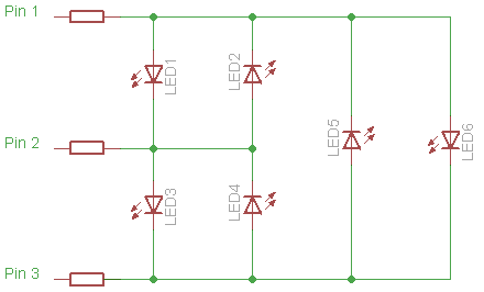
Pairs of LEDs are connected in anti-parallel (as opposed to parallel) connection and when the current is driven in one direction (Pin 1 to Pin 2 in the diagram below), one diode allows current to pass (LED1 lights up) while LED2 does not. Then when the current is reversed - ie from Pin 2 to Pin 1, LED1 does not allow current to pass, but LED2 does, and so it lights up this time.

So, by alternating the direction of relative polarity of Pin 1 and Pin 2, LED1 or LED2 can be made to glow.
This can be expanded to three pairs of LEDs using only one extra pin:
Not wanting to be uncomplicated, I decided to build a 4 x 3 LED array - Charlieplex style. I used some Perfboard which required some intricate soldering, but this was quite enjoyable, even though I didn't get it right first (or even 2nd) time.
Here's my circuit:

I have indicated which digital pins on the Arduino to use - 2, 3, 4 and 5. If you want to expand the number of LEDs, then more Arduino pins will be needed.
I got the inspiration for all this, from the excellent Arduino Cookbook 2nd Edition, 2012, by Michael Margolis. I slightly modified his circuit diagram and his code to do what I wanted it to do. His code very cleverly makes it easy to program increasing numbers of LEDs using more and more Arduino pins.
Here's the code:
1:  /*
2:   * Charlieplexing sketch by Michael Margolis Arduino Cookbook 2nd Ed
3:   * light 12 LEDs in sequence that are connected to pins 2, 3, 4 and 5
4:   */
5:
6:  int pins[] = {2,3,4,5}; // the pins that are connected to LEDs
7:
8:  // the next two lines infer number of pins and LEDs from the above array
9:  const int NUMBER_OF_PINS = sizeof(pins)/ sizeof(pins[0]);
10:  const int NUMBER_OF_LEDS = NUMBER_OF_PINS * (NUMBER_OF_PINS-1);
11:
12:  byte pairs[NUMBER_OF_LEDS/2][2] = { {0,1}, {1,2}, {2,3}, {0,2}, {1,3}, {0,3} }; // maps pins to LEDs
13:  // (0,1) refers to pin2 to pin3, (LED1 and LED2),(1,2) refers to pin3 to pin4 etc etc
14:  void setup()
15:  {
16:    // nothing needed here
17:  }
18:
19:  void loop(){
20:    for(int i=0; i < NUMBER_OF_LEDS; i++)
21:    {
22:      lightLed(i); // light each LED in turn
23:      delay(1000);
24:    }
25:  }
26:
27:  // this function lights the given LED, the first LED is 0
28:  void lightLed(int led)
29:  {
30:   // the following four lines convert LED number to pin numbers
31:   int indexA = pairs[led/2][0];
32:   int indexB = pairs[led/2][1];
33:   int pinA = pins[indexA];
34:   int pinB = pins[indexB];
35:
36:   // turn off all pins not connected to the given LED
37:   for (int i=0; i < NUMBER_OF_PINS; i++)
38:    if (pins[i] != pinA && pins[i] != pinB)
39:    { // if this pin is not one of our pins
40:      pinMode(pins[i], INPUT);  // set the mode to input
41:      digitalWrite(pins[i],LOW); // make sure pull-up is off
42:    }
43:   // now turn on the pins for the given LED
44:   pinMode(pinA, OUTPUT);
45:   pinMode(pinB, OUTPUT);
46:   if( led % 2 == 0)
47:   {
48:     digitalWrite(pinA,LOW);
49:     digitalWrite(pinB,HIGH);
50:   }
51:   else
52:   {
53:     digitalWrite(pinB,LOW);
54:     digitalWrite(pinA,HIGH);
55:   }
56:  }
57:
58:
The comments in the code are self-explanatory, but notice that each of the 4 pins has to be changed for each step through the program: when two of the pins are selected to determine the current path and hence which LED is to be lit up, the other 2 pins must be made to be INPUT pins rather than OUTPUT pins. The 'truth' table is as follows:
Pins:
|
LEDs:
|
||||||||||||||||
2
|
3
|
4
|
5
|
1
|
2
|
3
|
4
|
5
|
6
|
7
|
8
|
9
|
10
|
11
|
12
|
||
L
|
H
|
i
|
i
|
1
|
0
|
0
|
0
|
0
|
0
|
0
|
0
|
0
|
0
|
0
|
0
|
||
H
|
L
|
i
|
i
|
0
|
1
|
0
|
0
|
0
|
0
|
0
|
0
|
0
|
0
|
0
|
0
|
||
i
|
L
|
H
|
i
|
0
|
0
|
1
|
0
|
0
|
0
|
0
|
0
|
0
|
0
|
0
|
0
|
||
i
|
H
|
L
|
i
|
0
|
0
|
0
|
1
|
0
|
0
|
0
|
0
|
0
|
0
|
0
|
0
|
||
i
|
i
|
L
|
H
|
0
|
0
|
0
|
0
|
1
|
0
|
0
|
0
|
0
|
0
|
0
|
0
|
||
i
|
i
|
H
|
L
|
0
|
0
|
0
|
0
|
0
|
1
|
0
|
0
|
0
|
0
|
0
|
0
|
||
L
|
i
|
H
|
i
|
0
|
0
|
0
|
0
|
0
|
0
|
1
|
0
|
0
|
0
|
0
|
0
|
||
H
|
i
|
L
|
i
|
0
|
0
|
0
|
0
|
0
|
0
|
0
|
1
|
0
|
0
|
0
|
0
|
||
i
|
L
|
i
|
H
|
0
|
0
|
0
|
0
|
0
|
0
|
0
|
0
|
1
|
0
|
0
|
0
|
||
i
|
H
|
i
|
L
|
0
|
0
|
0
|
0
|
0
|
0
|
0
|
0
|
0
|
1
|
0
|
0
|
||
L
|
i
|
i
|
H
|
0
|
0
|
0
|
0
|
0
|
0
|
0
|
0
|
0
|
0
|
1
|
0
|
||
H
|
i
|
i
|
L
|
0
|
0
|
0
|
0
|
0
|
0
|
0
|
0
|
0
|
0
|
0
|
1
|
The pins are set to either OUTPUT with a pulse-on (H) or pulse-off (L) condition or as INPUT (i).
And here's my handiwork:

The Perfboard has parallel copper strips, which run left-to-right, at the back of the board, so that the horizontal rows of perforations are joined, while the vertical columns are not. The next photo shows the underside of the board:

You can see the horizontal copper strips, and you may be able to see (click the image to magnify) where I needed to break the horizontal connection in 4 places (corresponding to the 4 resistors) by using a small drill bit.
I calculated that for each resistor to reduce the Arduino's 5V pulses to be 2V across each LED, with a forward current i of 20 mA, the voltage V across the resistor would need to be 3V, and for a current i of 0.02 A, from Ohm's Law - R = V / i , the resistance's value R would have to be 3 / 0.02 = 150 Ω. (Here's a very useful LED resistor calculator for future use - http://www.hebeiltd.com.cn/?p=zz.led.resistor.calculator).
So I used 4 x 150 Ω resistors - remember that only one LED will be addressed at a time, so even though there are 12 LEDs, you only need one resistor to correspond to each Arduino pin.
And here's the video:
One of the drawbacks of Charlieplexing is that if a single LED fails, then it can be catastrophic for the whole display. I discovered that when I was doing the soldering - one poor joint or mistake in the connections, and the whole thing was seriously affected.
Of course, with Charlieplexing it's possible to display patterns and even scrolling patterns, where Persistence of Vision (POV) is employed to make it appear that several LEDs are lit up at the same time. I'll attempt that some time - but not just now!!
In the meantime, if you reduce the delay at line 23 in the code listing above, from 1000 ms to 2 ms, you can see all the LEDs lit at the same time, with a slight flicker, and reducing this to 1 ms reduces the flicker (for me) to imperceptible.
Perfect!!
PS. Ever notice that car tail lights at night can appear to flicker? Those are the LED ones!!
No comments:
Post a Comment