Here's the previously-mentioned HAT (Hardware Attached on Top) that has been developed by Alex Eames of RasPi.TV and RasP.iO. This comes as a kit which is easy to solder together. The aim with this was to make it easy to carry out Arduino programming on the Raspberry Pi. So the scripts are in the Arduino language and are run on the built-in Atmel ATMEGA328P-PU (ie an Arduino) chip.
Having uploaded the Arduino sketch on the Arduino IDE from the Raspberry Pi, from that point on, the Pi itself does nothing more than supply power to the Arduino, although having said that, you could conceivably have Pi software that interacts with the Arduino, or even does something completely different.
Depending on the software that you write, the hat could be removed and all it would need then would be power to continue running the sketch. For £14 (delivered) within the UK, it represents great value.
There is an extremely clearly written e-book (Learning Arduino Programming with RasPiO Duino) available HERE. The book brings you from the very simple Blink sketch right up to using the analog inputs for fading LEDs using pulse-width modulation (PWM) and taking advantage of the eye-brain system's persistence of vision |(POV), previously explained in my post 15 HERE.
The sketch I am demonstrating is almost identical to my ATTiny85 code which I used in that post, which came originally from Instructables.com HERE.
Here's a picture of the RasPiO Duino hat mounted on my Raspberry Pi B+:
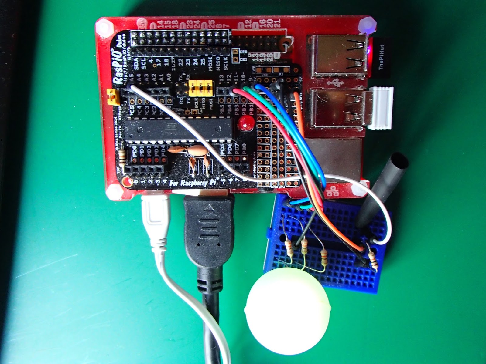
There's also a light dependent resistor (LDR) shown at the bottom centre, connected in series with a 10kΩ resistor to GND at one end, and Arduino pin 3 at the other end. In the above picture, the RGB LED is hidden under a light diffuser (A draft Guinness can widget). I also keep a 2 inch length of heat shrink over the LDR so that I can see the mood lamp working during the daylight hours.
The idea is of course, to program, through the Raspberry Pi, the Arduino chip, as a night-time mood lamp, cycling through all the colours in turn, provided there is minimal light reaching the LDR.
Here's a video where all is revealed:
and here's the code:
Must say, I do love mood lamps. Thanks Instructibles.com, and thanks Alex.
No comments:
Post a Comment