Here's another fantastic piece of technology - the gismo I will describe is a combination of 3-axis Gyroscope, 3-axis Accelerometer - and ... more!
This is it, mounted on the GY-521 breakout board, available from Amazon:
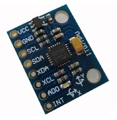
The whole board is about 20 mm by about 15 mm, and it cost £3.10 including delivery!! It comes with an 8-pin header which needs to be soldered on.
The black chip in the centre is the InvenSense MPU-6050 which contains a MEMS (Microelectromechanical System) gyroscope and MEMS accelerometer, all in one chip, called an Inertial Measurement Unit (IMU). Because each has 3 DOF [3 degrees of freedom (X, Y and Z outputs)], the IMU is said to have 6 degrees of freedom. The IMU also contains a microprocessor [embedded Digital Motion Processor (DMP)] which carries out some basic calculations involving quaternions. (That's where the maths become difficult). It even monitors its own chip temperature (and this can be read out) for real-time data correction.
However, apart from its very impressive performance, which is simple to understand, getting it to work is not easy, and understanding the extensive mathematics and the lengthy code is far from easy.
Gyroscope
Let me first explain what a gyroscope (or gyro) is: The early types of gyroscope included a spinning wheel of some kind. Because of the angular momentum involved, the device tries to maintain its position in space, and will resist forces which try to turn it away from its present position. One kind of electronic gyroscope uses a piezoelectric vibrating crystal which will also resist external forces. The device will generate an electrical signal when it detects such a Coriolis force and this signal can be processed to give information about the angular velocity, or rate of rotation about each of its axes. However, gyro readings 'creep' over time and so on its own, a gyro would not be useful for controlling orientation.Accelerometer
An accelerometer is a bit different. This device, also with micro-mechanical components, if falling freely, will generate no signal. On the other hand, an accelerometer at rest on the surface of the Earth will experience the acceleration due to gravity. If the device rotates on an axis other than the vertical, its resulting acceleration in the vertical direction will be an angular component of gravity. It could be moving fast, but if it's free falling or rotating freely, its output will say 'no acceleration'. So the accelerometer on its own would also not be enough to maintain orientation.Quaternions
The outputs from both the gyro and the accelerometer can be combined using a complementary filter or more accurately, using a Kalman filter. Geek Mom Debra at http://www.geekmomprojects.com/gyroscopes-and-accelerometers-on-a-chip/ gives a great explanation of how the complementary filter can combine the gyro and accelerometer data. Using quaternions, allowing angles of greater than 180 degrees to be calculated, provides an alternative to the Euler angle co-ordinate system which overcomes a problem known as gymbal lock. Gymbal lock occurs when two of the rotational axes come into alignment, thus reducing the number of degrees of freedom.Quaternions were conceived by Irish mathematician William Rowan Hamilton in 1843 as he crossed the Broom Bridge over Dublin's Royal Canal. Today they are fundamental to space ship, robotic and many other control systems as they give a means of avoiding a fourth gymbal in a gyroscope which would be necessary to overcome gymbal lock.
The in-built microprocessor (DMP) calculates the quaternions, and the Arduino sketch can output a stream of numbers representing rotations in all directions.
However, the Arduino Integrated Development Environment (IDE) doesn't have a graphical capability, so if a graphical representation is required, it's necessary to use a further coding IDE called the "Processing" IDE. The code, like Java, is quite similar to the Arduino sketch code.
Arduino code
Here's the Arduino code:
Processing code
and here's the Processing code which reads the Arduino data and performs some neat 3D drawing:
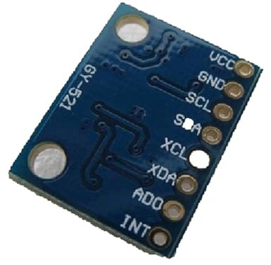
Here's the setup for power and the I 2C connections:
GY 521 VCC to Arduino 3.3V
GY 521 GND to Arduino GND
GY 521 SCL to Arduino Analog pin 5, A5
GY 521 SDA to Arduino Analog pin 4, A4
GY 521 INT (interrupt) to Arduino Digital pin 2

Here's the video: The window on the right shows the Processing IDE.
Here's the demo up close:
Until about 20 seconds into the 2nd video (10 s into the first video), the chip seems to go through a calibration routine, so that it 'gets its bearings' and it appears to monitor the degree of gyro creep, after which presumably a correction is applied to remove that creep. The vagueness in the above statement is because the manufacturers have not divulged the exact details about how this calibration is achieved.
After this stage in the video, the movement in 3 dimensions is caused by me rotating the mini breadboard containing the GY-521 and then moving it about so that it rotates about its X, Y and Z axes.
I must acknowledge Geek Mom Debra once more. Her excellent blog at http://www.geekmomprojects.com/mpu-6050-dmp-data-from-i2cdevlib/ is where I got her tweaked code, and I'm looking forward to seeing her "side-by-side comparison" between the embedded Digital Motion Processor and complementary filter data when it appears.
Note that the option I have chosen in the Arduino sketch is (lines 84 to 87):
// uncomment "OUTPUT_READABLE_QUATERNION" if you want to see the actual// quaternion components in a [w, x, y, z] format (not best for parsing// on a remote host such as Processing or something though)#define OUTPUT_READABLE_QUATERNION
The quaternion option is immune from gymbal lock. I found that the baud rate of 57600, which must be set the same on both Arduino and Processing code, worked best for me.
The aeroplane no longer, if turned through certain large angles, makes sudden 'flips' or simply freezes or even goes into what can only be described as 'the jitters'. The reference HERE tells the story about the Apollo 11 Moon mission on 20-Jul-69 when the IMU (Inertial Measurement Unit) froze due to gymbal lock.
Mmmmmmmm..... I wonder what this little device could be used for....
What's all this stuff about a teapot?? Well apparently the original demonstration used a 3-dimensional teapot which rotated. Now it's just a primitive plane, but it's still called a teapot!!